 搜索
搜索
 发布采购
发布采购
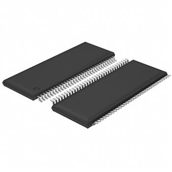
- 封装:64-TFSOP (0.240",6.10mm 宽)
- RoHS:无铅 / 符合限制有害物质指令(RoHS)规范要求
- 包装方式:Digi-Reel®
- 参考价格:$10.97-$9.86
更新日期:2024-04-01 00:04:00
产品简介:可带电插入 16 位 LVTTL 到 GTL/GTL+ 通用总线收发器
查看详情- 封装:64-TFSOP (0.240",6.10mm 宽)
- RoHS:无铅 / 符合限制有害物质指令(RoHS)规范要求
- 包装方式:Digi-Reel®
- 参考价格:$10.97-$9.86
SN74GTL1655DGGR 供应商
- 公司
- 型号
- 品牌
- 封装/批号
- 数量
- 地区
- 日期
- 说明
- 询价
-
TI
-
原厂原装
22+ -
3288
-
上海市
-
-
-
一级代理原装
-
TI
-
TSSOP-64
8 -
385
-
杭州
-
-
-
原装正品现货
-
TI/德州仪器
-
TSSOP64
21+ -
10000
-
杭州
-
-
-
只做原装现货,大量现货热卖
-
TI
-
-
2019+ -
5800
-
上海市
-
-
-
全新原装现货
-
TI(德州仪器)
-
TSSOP-64
2022+ -
12000
-
上海市
-
-
-
原装可开发票
-
TI代理
-
高频管
23+ -
15000
-
上海市
-
-
-
中国区代理原装进口特价
-
TI
-
TSSOP(DGG)|64
21+ -
3800
-
上海市
-
-
-
原装现货,品质为先!请来电垂询!
-
TI
-
TSSOP-64
22+ -
5000
-
常州
-
-
-
全新原装现货热卖
-
TI
-
TSSOP64
23+ -
5800
-
上海市
-
-
-
进口原装现货,杜绝假货。
SN74GTL1655DGGR 中文资料属性参数
- 标准包装:1
- 类别:集成电路 (IC)
- 家庭:逻辑 - 通用总线函数
- 系列:74GTL
- 逻辑类型:通用总线收发器
- 输入数:-
- 电路数:16 位
- 输出电流高,低:24mA,24mA
- 电源电压:3 V ~ 3.6 V
- 工作温度:-40°C ~ 85°C
- 安装类型:表面贴装
- 封装/外壳:64-TFSOP (0.240",6.10mm 宽)
- 供应商设备封装:64-TSSOP
- 包装:®
- 其它名称:296-1184-6
产品特性
- Member of the Texas Instruments Widebus™ Family
- UBT™ Transceiver Combines D-Type Latches and D-Type Flip-Flops for Operation in Transparent, Latched, or Clocked Modes
- OEC™ Circuitry Improves Signal Integrity and Reduces Electromagnetic Interference
- Translates Between GTL/GTL+ Signal Level and LVTTL Logic Levels
- High-Drive (100 mA), Low-Output-Impedance (12 ) Bus Transceiver (B Port)
- Edge-Rate-Control Input Configures the B-Port Output Rise and Fall Times
- Ioff, Power-Up 3-State, and BIAS VCC Support Live Insertion
- Bus Hold on Data Inputs Eliminates the Need for External Pullup/Pulldown Resistors on A Port
- Distributed VCC and GND Pins Minimize High-Speed Switching Noise
产品概述
The SN74GTL1655 is a high-drive (100 mA), low-output-impedance (12 ) 16-bit UBT™ transceiver that provides LVTTL-to-GTL/GTL+ and GTL/GTL+-to-LVTTL signal-level translation. This device is partitioned as two 8-bit transceivers and combines D-type flip-flops and D-type latches to allow for transparent, latched, and clocked modes of data transfer similar to the ’16501 function. This device provides an interface between cards operating at LVTTL logic levels and a backplane operating at GTL/GTL+ signal levels. Higher-speed operation is a direct result of the reduced output swing (<1 V), reduced input threshold levels, and OEC™ circuitry. The high drive is suitable for driving double-terminated low-impedance backplanes using incident-wave switching.The user has the flexibility of using this device at either GTL (VTT = 1.2 V and VREF = 0.8 V) or the preferred higher noise margin GTL+ (VTT = 1.5 V and VREF = 1 V) signal levels. GTL+ is the Texas Instruments derivative of the Gunning Transceiver Logic (GTL) JEDEC standard JESD 8-3. The B port normally operates at GTL or GTL+ signal levels, while the A-port and control inputs are compatible with LVTTL logic levels but are not 5-V tolerant. VREF is the reference input voltage for the B port.This device is uniquely partitioned as two 8-bit transceivers with individual latch timing and output signals, but with a common clock and output enable inputs for both transceiver words.Data flow for each word is determined by the respective latch enables (LEAB and LEBA), output enables (OEAB\ and OEBA\), and clock (CLK). The output enables (1OEAB\, 1OEBA\, 2OEAB\, and 2OEBA\) control byte 1 and byte 2 data for the A-to-B and B-to-A directions, respectively.For A-to-B data flow, the devices operate in the transparent mode when LEAB is high. When LEAB transitions low, the A data is latched independent of CLK high or low. If LEAB is low, the A data is registered on the CLK low-to-high transition. When OEAB\ is low, the outputs are active. With OEAB\ high, the outputs are in the high-impedance state.Data flow for the B-to-A direction is identical, but uses OEBA\, LEBA, and CLK. Note that CLK is common to both directions and both 8-bit words. (OE)\ is also common and is used to disable all I/O ports simultaneously.The SN74GTL1655 has adjustable edge-rate control (VERC ). Changing VERC input voltage between GND and VCC adjusts the B-port output rise and fall times. This allows the designer to optimize for various loading conditions.This device is fully specified for live-insertion applications using Ioff, power-up 3-state, and BIAS VCC . The Ioff circuitry disables the outputs, preventing damaging current backflow through the device when it is powered down. The power-up 3-state circuitry places the outputs in the high-impedance state during power up and power down, which prevents driver conflict. The BIAS VCC circuitry precharges and preconditions the B-port input/output connections, preventing disturbance of active data on the backplane during card insertion or removal, and permits true live-insertion capability.When VCC is between 0 and 1.5 V, the device is in the high-impedance state during power up or power down. However, to ensure the high-impedance state above 1.5 V, (OE)\ should be tied to VCC through a pullup resistor; the minimum value of the resistor is determined by the current-sinking capability of the driver.Active bus-hold circuitry holds unused or undriven LVTTL inputs at a valid logic state. Use of pullup or pulldown resistors with the bus-hold circuitry is not recommended.
SN74GTL1655DGGR 相关产品
- 74ALVCH16501DGGRG4
- 74LVTH16501DGGRE4
- CD74HC299E
- CD74HC299M96
- CD74HCT299E
- CD74HCT299M96
- CVMEH22501AIDGGREP
- CVMEH22501AIDGVREP
- GTLP18T612MTDX
- SN74ABT162500DL
- SN74ABT162601DGGR
- SN74ABT162601DLR
- SN74ABT16500BDGGR
- SN74ABT16500BDL
- SN74ABT16500BDLR
- SN74ABT16501DGGR
- SN74ABT16501DL
- SN74ABT16501DLR
- SN74ABT16601DGGR
- SN74ABT16601DL
- SN74ABT16601DLR
- SN74ABTH182502APM
- SN74ABTH182504APM
- SN74ABTH18502APM
- SN74ABTH18502APMR
- SN74ABTH18504APM
- SN74ABTH32316PN
- SN74ABTH32318PN
- SN74ALVC162334DGGR
- SN74ALVC162334DGVR