 搜索
搜索
 发布采购
发布采购
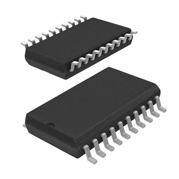
- 封装:20-SOIC(0.295",7.50mm 宽)
- RoHS:无铅 / 符合限制有害物质指令(RoHS)规范要求
- 包装方式:Digi-Reel®
- 参考价格:$0.363-$0.91
更新日期:2024-04-01 00:04:00
产品简介:具有三态输出的高速 CMOS 逻辑 8 位通用移位寄存器
查看详情- 封装:20-SOIC(0.295",7.50mm 宽)
- RoHS:无铅 / 符合限制有害物质指令(RoHS)规范要求
- 包装方式:Digi-Reel®
- 参考价格:$0.363-$0.91
CD74HC299M96 供应商
- 公司
- 型号
- 品牌
- 封装/批号
- 数量
- 地区
- 日期
- 说明
- 询价
-
TI
-
原厂原装
22+ -
3288
-
上海市
-
-
-
一级代理原装
-
TI(德州仪器)
-
SOIC-20
2022+ -
12000
-
上海市
-
-
-
原装可开发票
CD74HC299M96 中文资料属性参数
- 标准包装:1
- 类别:集成电路 (IC)
- 家庭:逻辑 - 通用总线函数
- 系列:74HC
- 逻辑类型:通用移位寄存器
- 输入数:-
- 电路数:8 位
- 输出电流高,低:7.8mA,7.8mA
- 电源电压:2 V ~ 6 V
- 工作温度:-55°C ~ 125°C
- 安装类型:表面贴装
- 封装/外壳:20-SOIC(0.295",7.50mm 宽)
- 供应商设备封装:20-SOIC
- 包装:®
- 其它名称:296-14520-6
产品特性
- Buffered Inputs
- Four Operating Modes: Shift Left, Shift Right, Load and Store
- Can be Cascaded for N-Bit Word Lengths
- I/O0 – I/O7 Bus Drive Capability and Three-State for Bus Oriented Applications
- Typical fMAX = 50MHz at VCC =5V, CL = 15pF, TA = 25°C
- Fanout (Over Temperature Range) Standard Outputs. . . . . 10 LSTTL Loads Bus Driver Outputs . . . . . . 15 LSTTL Loads
- Standard Outputs. . . . . 10 LSTTL Loads
- Bus Driver Outputs . . . . . . 15 LSTTL Loads
- Wide Operating Temperature Range . . . –55°C to 125°C
- Balanced Propagation Delay and Transition Times
- Significant Power Reduction Compared to LSTTL Logic ICs
- HC Types 2V to 6V Operation High Noise Immunity: NIL = 30%, NIH = 30% of VCC at VCC = 5V
- 2V to 6V Operation
- High Noise Immunity: NIL = 30%, NIH = 30% of VCC at VCC = 5V
- HCT Types 4.5V to 5.5V Operation Direct LSTTL Input Logic Compatibility, VIL = 0.8V (Max), VIH = 2V (Min) CMOS Input Compatibility, Il 1µA at VOL, VOH
- 4.5V to 5.5V Operation
- Direct LSTTL Input Logic Compatibility, VIL = 0.8V (Max), VIH = 2V (Min)
- CMOS Input Compatibility, Il 1µA at VOL, VOH
产品概述
The ’HC259 and ’HCT299 are 8-bit shift/storage registers with three-state bus interface capability. The register has four synchronous-operating modes controlled by the two select inputs as shown in the mode select (S0, S1) table. The mode select, the serial data (DS0, DS7) and the parallel data (I/O0 – I/O7) respond only to the low-to-high transition of the clock (CP) pulse. S0, S1 and data inputs must be one set-up time prior to the clock positive transition.The Master Reset (MR)\ is an asynchronous active low input. When MR\ output is low, the register is cleared regardless of the status of all other inputs. The register can be expanded by cascading same units by tying the serial output (Q0) to the serial data (DS7) input of the preceding register, and tying the serial output (Q7) to the serial data (DS0) input of the following register. Recirculating the (n x 8) bits is accomplished by tying the Q7 of the last stage to the DS0 of the first stage.The three-state input/output I(/O) port has three modes of operation:1. Both output enable (OE1\ and OE2\) inputs are low and S0 or S1 or both are low, the data in the register is presented at the eight outputs.2. When both S0 and S1 are high, I/O terminals are in the high impedance state but being input ports, ready for par-allel data to be loaded into eight registers with one clock transition regardless of the status of OE1\ and OE2\.3. Either one of the two output enable inputs being high will force I/O terminals to be in the off-state. It is noted that each I/O terminal is a three-state output and a CMOS buffer input.
CD74HC299M96 数据手册
| 数据手册 | 说明 | 数量 | 操作 |
|---|---|---|---|
 CD74HC299M96 CD74HC299M96
|
Universal Shift Register 8-Bit 20-SOIC |
20页,869K | 查看 |
CD74HC299M96 相关产品
- 74ALVCH16501DGGRG4
- 74LVTH16501DGGRE4
- CD74HC299E
- CD74HCT299E
- CD74HCT299M96
- CVMEH22501AIDGGREP
- CVMEH22501AIDGVREP
- GTLP18T612MTDX
- SN74ABT162500DL
- SN74ABT162601DGGR
- SN74ABT162601DLR
- SN74ABT16500BDGGR
- SN74ABT16500BDL
- SN74ABT16500BDLR
- SN74ABT16501DGGR
- SN74ABT16501DL
- SN74ABT16501DLR
- SN74ABT16601DGGR
- SN74ABT16601DL
- SN74ABT16601DLR
- SN74ABTH182502APM
- SN74ABTH182504APM
- SN74ABTH18502APM
- SN74ABTH18502APMR
- SN74ABTH18504APM
- SN74ABTH32316PN
- SN74ABTH32318PN
- SN74ALVC162334DGGR
- SN74ALVC162334DGVR
- SN74ALVC162334DLR