 搜索
搜索
 发布采购
发布采购
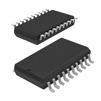
- 封装:20-SOIC(0.295",7.50mm 宽)
- RoHS:无铅 / 符合限制有害物质指令(RoHS)规范要求
- 包装方式:带卷 (TR)
- 参考价格:$0.658
更新日期:2024-04-01 00:04:00
产品简介:具有总线保持、TTL 兼容型 CMOS 输入和三态输出的 8 通道、2.7V 至 3.6V 反相器
查看详情- 封装:20-SOIC(0.295",7.50mm 宽)
- RoHS:无铅 / 符合限制有害物质指令(RoHS)规范要求
- 包装方式:带卷 (TR)
- 参考价格:$0.658
SN74LVTH540DWR 供应商
- 公司
- 型号
- 品牌
- 封装/批号
- 数量
- 地区
- 日期
- 说明
- 询价
-
TI
-
原厂原装
22+ -
3288
-
上海市
-
-
-
一级代理原装
-
TI(德州仪器)
-
SOIC-20
2022+ -
12000
-
上海市
-
-
-
原装可开发票
SN74LVTH540DWR 中文资料属性参数
- 标准包装:2,000
- 类别:集成电路 (IC)
- 家庭:逻辑 - 栅极和逆变器
- 系列:74LVTH
- 逻辑类型:逆变器,缓冲器
- 电路数:1
- 输入数:8
- 特点:三态
- 电源电压:2.7 V ~ 3.6 V
- 电流 - 静态(最大值):5mA
- 输出电流高,低:32mA,64mA
- 逻辑电平 - 低:0.8V
- 逻辑电平 - 高:2V
- 额定电压和最大 CL 时的最大传播延迟:2.7ns @ 3.3V,50pF
- 工作温度:-40°C ~ 85°C
- 安装类型:表面贴装
- 供应商设备封装:20-SOIC
- 封装/外壳:20-SOIC(0.295",7.50mm 宽)
- 包装:带卷 (TR)
产品特性
- Support Mixed-Mode Signal Operation (5-V Input and Output Voltages With 3.3-V VCC)
- Typical VOLP (Output Ground Bounce) <0.8 V at VCC = 3.3 V, TA = 25°C
- Support Unregulated Battery Operation Down to 2.7 V
- Ioff and Power-Up 3-State Support Hot Insertion
- Bus Hold on Data Inputs Eliminates the Need for External Pullup/Pulldown Resistors
- Latch-Up Performance Exceeds 500 mA Per JESD 17
- ESD Protection Exceeds JESD 22 2000-V Human-Body Model (A114-A) 200-V Machine Model (A115-A)
- 2000-V Human-Body Model (A114-A)
- 200-V Machine Model (A115-A)
产品概述
These octal buffers/drivers are designed specifically for low-voltage (3.3-V) VCC operation, but with the capability to provide a TTL interface to a 5-V system environment.The ’LVTH540 devices are ideal for driving bus lines or buffer memory address registers. These devices feature inputs and outputs on opposite sides of the package that facilitate printed circuit board layout.The 3-state control gate is a 2-input AND gate with active-low inputs so that if either output-enable (OE1\ or OE2\) input is high, all outputs are in the high-impedance state.Active bus-hold circuitry holds unused or undriven inputs at a valid logic state. Use of pullup or pulldown resistors with the bus-hold circuitry is not recommended.When VCC is between 0 and 1.5 V, the devices are in the high-impedance state during power up or power down. However, to ensure the high-impedance state above 1.5 V, OE\ should be tied to VCC through a pullup resistor; the minimum value of the resistor is determined by the current-sinking capability of the driver.These devices are fully specified for hot-insertion applications using Ioff and power-up 3-state. The Ioff circuitry disables the outputs, preventing damaging current backflow through the devices when they are powered down. The power-up 3-state circuitry places the outputs in the high-impedance state during power up and power down, which prevents driver conflict.
SN74LVTH540DWR 数据手册
| 数据手册 | 说明 | 数量 | 操作 |
|---|---|---|---|
 SN74LVTH540DWR SN74LVTH540DWR
|
Buffer, Inverting 1 Element 8 Bit per Element Push-Pull Output 20-SOIC |
17页,880K | 查看 |
SN74LVTH540DWR 相关产品
- 1A1G04QDBVRG4Q1
- 1P1G08MDBVREPG4
- 1P1G14MDBVREPG4
- 74ABT240CSCX
- 74ABT240DB,118
- 74AC00SJX
- 74AC04SJX
- 74AC11000DR
- 74AC11000N
- 74AC11004DWR
- 74AC11004N
- 74AC11008D
- 74AC11008N
- 74AC11008PWR
- 74AC11032D
- 74AC11032DBR
- 74AC11032N
- 74AC11032NSR
- 74AC11086D
- 74AC11086N
- 74AC11240DBR
- 74AC11240DW
- 74AC11240PW
- 74AC11SJX
- 74AC14SJ
- 74AC20PC
- 74AC240MTCX
- 74AC240MTR
- 74AC240SC
- 74AC32SJ